

X-Ray Nondestructive Inspection System
Nano-focus TXLamino
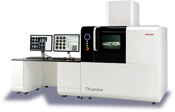
| Applications | High-density chip mounted boards, small surface-mount electric components, small connectors, small automotive electronic parts, resins, GFRP, CFRP, etc. |
|---|
The TXLamino allows efficient inspection of circuit boards with BGAs, CSPs, highly integrated semiconductor packages, flip chips, etc. Equipped with a six-axis sample manipulator, TXLamino allows you to capture oblique fluoroscopic images of specific areas to be inspected and view device-to-board bonds in 3D by capturing images from 360 degrees.

FEATURES
Nano-focus X-ray generator and high-definition X-ray detector
By changing the filament, you can choose an X-ray focal spot size from 0.25 μm or 0.8 μm.
The TXLamino comes with a 4K monitor, a high-definition X-ray detector, and a 4-megapixel camera to achieve high-resolution imaging.
Oblique CT (Lamino CT) included as a standard feature
The oblique CT unit provides functions to automatically track the center of the field of view while a sample is tilted and rotated and reduce blurring during imaging.
And the optional vertical CT and heating units enable simulation and high-definition image analysis under a range of scenarios.
Meeting a variety of needs for guided and advanced operations
You can select either a guided or advanced operation according to your level of expertise.
In Guided mode, which provides guidance on CT scanning operations, anyone can capture clear images easily.
The Advanced mode allows you to set more detailed scan conditions than the Guided mode.
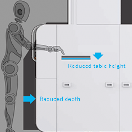
Ergonomic design
The size and position of the sample door have been modified. With two door openings, sample setup and maintenance are now easier.
The door has a window for observing samples.
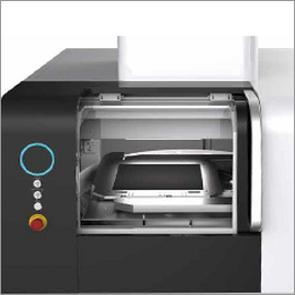
Door with two openings
IMAGE EXAMPLES
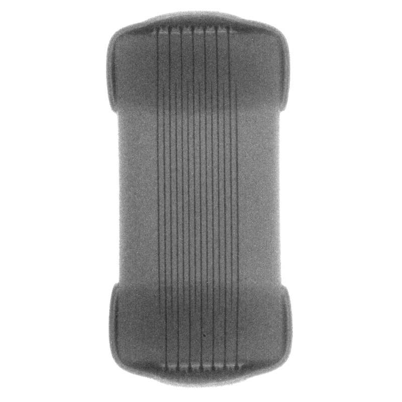
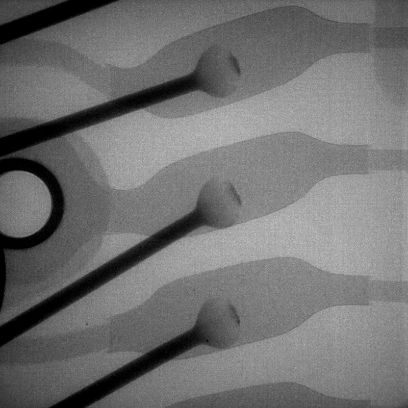
Fluoroscopic image of a
chip capacitor
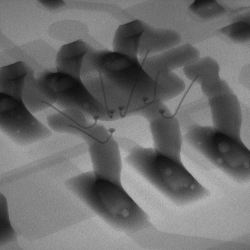
Fluoroscopic image of
IC bonding wires
Oblique fluoroscopic image of
IC soldering voids
SPECIFICATION
| Key Specifications | |
|---|---|
| Model | TXL-6160nID |
| X-ray generator | Open, transmissive |
| Tube voltage / current (max) | 160 kV / 200 μA |
| X-ray focal spot size | 0.25μm |
| X-ray detector | High-definition X-ray I.I. (4-inch / 2-inch)∗ |
| Camera’s effective pixel count | 4 megapixels |
| Camera’s output grayscale level | 16-bit |
| Mechanical unit | 6-axis |
| X/Y-stage stroke | 300×300mm |
| Stage rotation | 0° to 360° (horizontal) |
| Tilting stroke | 0° to 60° |
| FOV tracking function | Automatic tracking of the center of the field of view while a sample is tilted and rotated |
| Oblique CT (Lamino CT) scanner | CT data acquisition (at arbitrary tilting angles) |
| External dimensions (W x D x H) | Shield cabinet: Approx. 1600×1600×2000 mm Operation panel: Approx. 1600×800×750 mm (desk height) |
| Leakage dose | 1 μSv/h or less |
| Applications | High-density circuit boards, various electronic parts, etc. |
∗ X-ray I.I.: X-ray image intensifier
| Image analysis and measurement functions | |
|---|---|
| Measurement functions | Wettability, wire sweep, point-to-point distance, BGA void calculation |
| Analysis functions | Pseudo-color images, profiles, histograms, 3D rendering |
| Optional CT functions | |
|---|---|
| Vertical CT (cone beam CT) | Vertical CT unit (configurable by exchanging the sample stage) |
| Heating unit (Heater type) | Maximum temperature: 300°C, maximum rate of temperature rise: 60°C/min (Air and N2 gas can be purged.) |
| Heating unit (Wave type) | Maximum temperature: 300°C, maximum rate of temperature rise: 5°C/min (Air and N2 gas can be purged.) |
CASE EXAMPLE
Oblique CT (Lamino CT) images of a BGA
The following shows the oblique fluoroscopic and CT images of a BGA.
When a sample is placed on the turntable between the X-ray generator and the X-ray detector, it is rotated through 360 degrees to obtain a fluoroscopic image.
The captured images are then reconstructed in 3D.
Oblique fluoroscopic
image of a BGA
Oblique CT (Lamino CT)
image of a BGA
Simulation analysis of reflow soldering using a heating unit
The following video shows a chip resistor on a board while it is heated.
Cream solder begins to melt at roughly 215°C, creating a bond between the chip resistor and the board.
This function allows you to analyze the reflow soldering process and observe the condition of an electronic component while it is heated.
Video showing a chip resistor being heated